Action camera mounts
Configure the bolt pattern, camera angle, base shape, sleeve connector, and mounting access.
On this page
Start with a prepared sleeveMatch the frameSet the camera positionShape the baseFit the sleeve connectorMake room for installationSave and exportStart with a prepared sleeve#
Choose a sleeve from the library or finish preparing your own, then select 02 Mount. Mount Maker creates the base automatically around the selected bolt pattern.
Match the frame#
Select a two- or four-screw layout and measure between hole centers. Four-bolt layouts have independent Front bolt width and Rear bolt width controls. Set the front-to-rear spacing and choose M2, M2.5, M3, or a custom hole diameter.
A saved drone profile can apply these measurements. Confirm that its frame revision and dimensions match your hardware. Profiles record user-supplied measurements, not a verified fit guarantee.
Head diameter controls the screw-head recess diameter. Pocket depth = 0 leaves a plain through hole. Recessed heads must retain material beneath them; the generator checks for at least 1 mm of base below the recess.
Set the camera position#
Adjust Angle to pitch the sleeve. Lift above base raises it and extends its support. Rest sleeve on base returns lift to zero, seating the angled sleeve against the base.
Under advanced adjustments, Move left / right and Move front / back shift the sleeve over the fixed bolt pattern. Review overhangs and camera access after moving it.
Shape the base#
The base sizes itself around the holes and the material needed beside them. The curved base has a continuous middle section with rounded bolt fingers. Independent Front arm length and Rear arm length controls adjust its camera gaps; shorter bolt patterns may limit those controls to preserve the middle web.
Choose Solid base for a full rounded plate. Two-bolt layouts use a rounded bar. These options change the footprint; they do not provide a strength simulation.
Fit the sleeve connector#
Fit connector to sleeve sizes the connection from the sleeve's lower shell and follows its underside. Disable it to enter a manual Connector width and Connector depth.
Enable Round connector into base to add an adjustable fillet. Inspect the underside and camera cavity after changing the connector, especially with unusual imported sleeves. The fitted support does not infer the intended fit of an arbitrary source mesh.
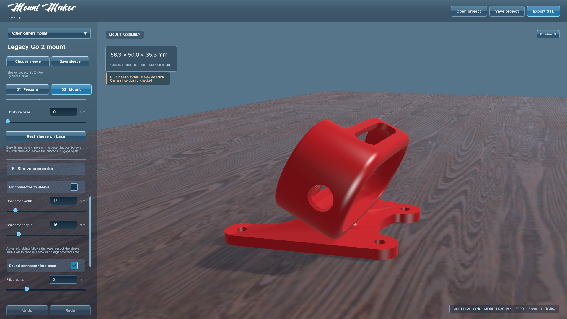
Earlier projects preserve their previous support geometry until you enable the new fit option or choose Use the new base & seating. Save a copy before making a substantial migration.
Make room for installation#
Add bolt access holes deliberately removes obstructing material above selected bolts. It is off by default. Use Show cut preview to inspect the numbered removed volumes before exporting.
Automatic access diameter uses the larger of the screw head or tool diameter, plus 0.6 mm of diametral clearance. Advanced controls allow individual bolts, a custom diameter, and a limited cut height. Through entire mount opens the full vertical path.
These cuts can affect camera-retaining walls even when the result remains connected. Review Clearance & fit checks and test the actual print.
Save and export#
Choose Save project for the complete editable design. Export from Mount to include the base and support. Exporting from Prepare saves the prepared sleeve instead.
Something unclear? Let us know.