
Antenna & GPS mounts
Combine rear antenna tubes, an optional GPS tray, and a lower T-antenna holder into one connected mount.
On this page
Fit the rear standoffsSet up the upper antennasAdd a GPS trayAdd a lower T-antennaInspect the fitSave and exportFit the rear standoffs#
Choose Rear antenna mount in the design selector. Enter rear standoff center spacing, diameter, and sleeve height. If applying a saved drone profile, confirm its measurements describe the rear of your frame.
Set up the upper antennas#
Choose one or two upper antennas. Solid tube is the default, with a starting inside diameter of 6 mm. Measure the antenna stem and any connector that must pass through; the starting value is not a universal fit.
Cable slit + zip tie groove opens the back of the tube and adds a retaining groove. Adjust tube length, rearward lean, and pair spread using the sliders or number fields.
The tube roots join a shared support block between the standoff sleeves. If the roots cannot fit, use smaller tubes, one antenna, or greater standoff spacing as appropriate for the real frame. The app rejects incompatible dimensions instead of committing a broken shape.
Add a GPS tray#
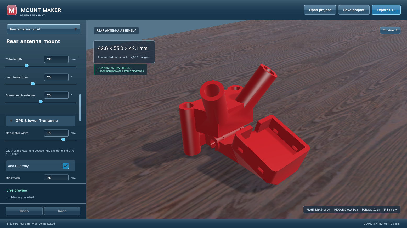
Expand GPS & lower T-antenna and enable the GPS tray. Set its internal width, depth, and pocket height to suit the complete device. Extra reach behind frame moves only the GPS tray farther back. Tilt tray back angles the pocket.
The tray includes side tie slots and a front cable opening. Lip over GPS adds retaining rails over the sides of the device. It follows the tray tilt and preserves the cable and tie openings.
Adding the GPS tray does not raise the upper antenna tubes. Check clearance to the actual battery, frame, props, cables, and antenna heads; those shapes are not modeled.
Add a lower T-antenna#
Enable the lower T holder and enter the measured crossbar and cable-neck dimensions. Its own reach control places it behind the frame independently of the GPS tray. The crossbar loads from below and has two retaining tie grooves.
Connector width changes the shared lower connection across the drone. A separate lower member supports the GPS/T assembly, with a gap for cable access below the upper antenna block. If the height cannot accommodate the members and gap, increase sleeve height as prompted.
Inspect the fit#
Under Advanced fit & strength, adjust standoff fit allowance, sleeve and tube walls, slit width, and GPS side clearance. Display-only hardware guides help you inspect approximate positions. They are excluded from export.
The GPS box is checked against the printed mount, but the tool does not represent the full aircraft. This generator does not provide SMA mounts or large antenna-head cups.
Save and export#
Export STL saves one connected mount positioned on Z = 0. Choose orientation and supports in your slicer. Save project stores the editable recipe and compatibility details without needing a source STL. Print a sample to check TPU grip and component retention before flying.
Something unclear? Let us know.