FPV camera soft mounts
Make paired tabs for existing standoffs, with camera-width adjustment and fixed or adjustable tilt.
On this page
Measure the hardwarePlace the cameraChoose a tilt styleCheck camera movementExport the tabsMeasure the hardware#
Choose FPV camera soft mount in the design selector. Enter the standoff center spacing, standoff diameter, and sleeve height. These parts slip over existing standoffs; they do not replace the standoffs themselves.
Enter the camera width and select one or two M2 screws per side. A saved drone profile can supply standoff spacing and diameter, but sleeve height remains a separate setting. Check that the profile describes the front of the frame.
Place the camera#
The tabs adapt the mounting width inward or outward and position the camera forward of the standoffs. Screw center height is measured from the lower frame plate at zero tilt. With two screws per side, it describes the midpoint between their centers.
Upper screw forward sets the front-to-back difference between the upper and lower screw centers. Use measured camera dimensions rather than an approximate visual match.
Choose a tilt style#
For two-screw cameras, choose fixed round holes, an upper pivot with a lower arc, a lower pivot with an upper arc, or two arcs around the midpoint. Adjustable designs start at zero degrees and default to a 25-degree maximum, configurable up to 45 degrees.
For one-screw cameras, a round pivot hole holds the angle through tightening. The maximum angle defines the range checked for clearance; it is not a mechanical stop.
Check camera movement#
Use Check camera movement to sweep the display-only camera guide through the tilt range. The guide's rectangular body is centered on the screw pattern. Its lens marker only indicates the forward direction; it does not reproduce your lens shape.
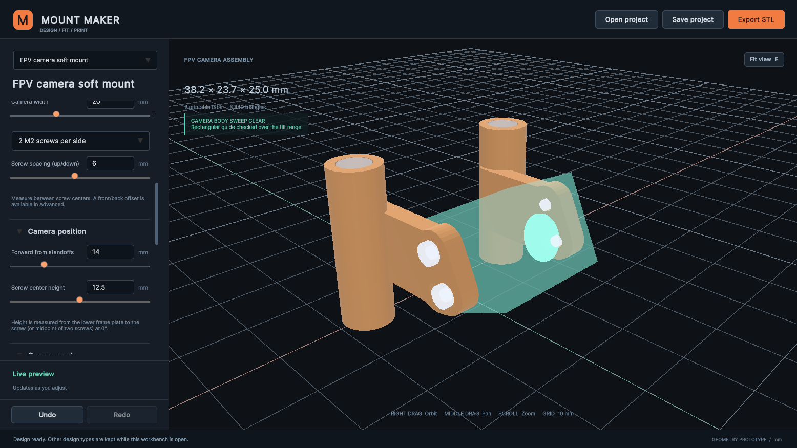
Advanced controls include the body depth and height, side gap, M2 clearance diameter, standoff allowance, walls, border, and connecting web height. Match web to screw span keeps the web sized to the screw and slot span within the sleeve height. Disable it for a manual height.
The movement check uses a conservative envelope. It may flag space that the real camera never occupies. It also does not model wires, screw length, driver access, or real frame cutouts. Inspect the result against your complete build.
Export the tabs#
Print parts chooses both tabs, the left tab, or the right tab for STL export. When exporting both, the parts are separated and translated onto the build plane. Their position is not an optimized print orientation; upright sleeves can leave elevated arms needing support.
Save project keeps the full editable pair, including author and camera/frame details. No source STL is required. FPV projects cannot be saved as action-camera sleeve assets.
TPU fit, vibration behavior, retention, and strength need physical testing. These tabs use solid connecting arms; they do not include tuned shock-absorbing patterns.
Something unclear? Let us know.