Arm feet from photos
Calibrate an underside photo, trace the carbon outline, and generate a foot using measured fit dimensions.
On this page
Start with a useful photographScrews and scaleFit the outlineSet the physical fitApply or keep a draftStart with a useful photograph#
Choose Arm foot from photo. Import a JPG or PNG underside photo, or begin with the illustrative starting foot. Use a clear view of the arm edge and screw centers. Measure the real screw spacing and carbon thickness separately.
The photo provides an outline reference. The editor does not reconstruct hidden edges or infer the arm thickness for you.
Screws and scale#
Mark the screw centers and select M2, M3, or Custom. The first two centers establish scale from their measured separation.
Four centers clicked in order around a known rectangular pattern also allow perspective correction. Use the actual pattern dimensions, not a guess from the image. Photo tools let you adjust reference and rotation without discarding the markers.
Screw-hole and head sizes appear over the photo. A central shaft recess is off by default; enable it only if needed and set its diameter and depth.
Fit the outline#
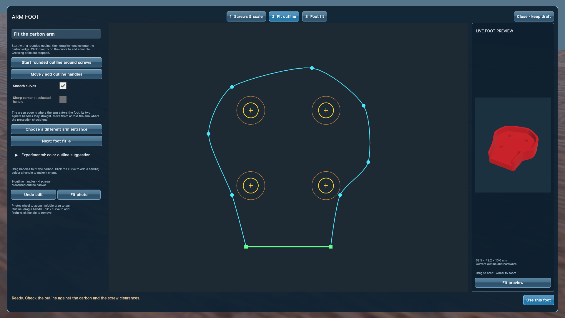
Start a rounded outline around the screws and drag its handles to the carbon edge. Click directly on a curve to add a handle. Right-click a handle to remove it, or select it and choose a sharp corner.
The green edge and square handles define the straight arm entrance. Place that entrance where the protection should end. The editor supports asymmetric and concave outlines, while stopping crossing or collapsing edits.
Smooth outlines support up to 32 handles. Use enough points to describe the arm without adding unnecessary tiny features. The color-based suggestion under Experimental is not reliable motor recognition.
Set the physical fit#
In Foot fit, enter arm thickness, foot height, and fit allowance. The adjacent 3D preview updates as you edit; drag to orbit and scroll to zoom.
Conflicting shaft and hole circles turn red. The previous preview dims and cannot be applied until you correct the dimensions. Correcting them keeps your outline.
The generator creates a flat landing floor. Inspect its contact with your actual arm and make a test print before choosing final allowances.
Apply or keep a draft#
Use this foot commits the edit to the workbench as one global undo step. Save a portable .mmproject or export the STL there.
Close · keep draft returns to the workbench while keeping the unfinished local draft. Resume saved foot draft restores it, including its photograph, even if calibration or hardware conflicts were unfinished. This recovery slot is replaced as another draft is edited; it is separate from a saved printable project.
Finished projects include the photo and calibration. Check the photograph for private details before sharing the project with other people.
Something unclear? Let us know.